OSPF Forwarding Address including NSSA- PART 1

So back to OSPF again , this time i am going deal with Forwarding address and why we need forwarding address ,what are the advantages of it and what happens in NSSA ?

As we all know the FA would be set in the following conditions:

Snippets from www.cisco.com

  • OSPF is enabled on the ASBR’s next hop interface AND
  • ASBR’s next hop interface is non-passive under OSPF AND
  • ASBR’s next hop interface is not point-to-point AND
  • ASBR’s next hop interface is not point-to-multipoint AND
  • ASBR’s next hop interface address falls under the network range specified in the router ospf command.

“But if  we have NSSA in OSPF the FA is set by default in the NSSA ASBR unless the NSSA ABR suppresses the FA when it converts the type 7 LSA to type 5 LSA”

We are redistributing a prefix in IOU1 so that it can generate a type 7 NSSA LSA and the NSSA can generate type 5 LSA to the other areas .

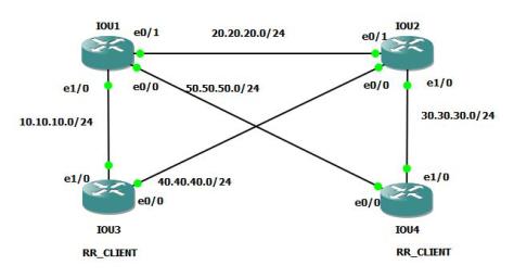
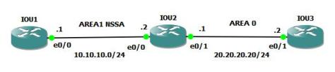
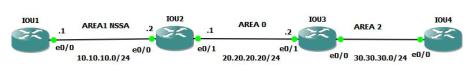
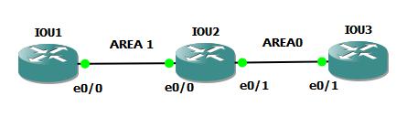
So here is our scenario for this topic:screenshot_2-jpeg

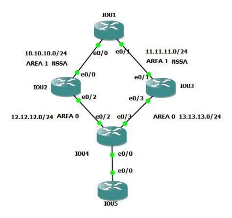
” As we all know the NSSA ABR with the highest router-id converts the Type 7 LSA to Type 5 LSA though both the NSSA ABR’s can convert if we have nssa-translate always command in both the ABR’s .So in this case the IOU3 converts the Type 7 to Type 5 LSA “

The configurations of the routers are as follows:

OSPF is configured on the interfaces directly without using Network command.

IOU1#show run | s ospf
ip ospf 1 area 1
ip ospf 1 area 1
router ospf 1
area 1 nssa
redistribute connected subnets route-map test

IOU1#show route-map test
route-map test, permit, sequence 10
Match clauses:
ip address (access-lists): 10
Set clauses:
Policy routing matches: 0 packets, 0 bytes

IOU1#show ip access-lists
Standard IP access list 10
10 permit 1.1.1.0, wildcard bits 0.0.0.255 (1 match)

IOU2#sh run | s ospf
ip ospf 1 area 1
ip ospf 1 area 0
router ospf 1
area 1 nssa

IOU3#show run | s ospf
ip ospf 1 area 1
ip ospf cost 40
ip ospf 1 area 0
router ospf 1
area 1 nssa

IOU4#show run | s ospf
ip ospf 1 area 2
ip ospf 1 area 0
ip ospf 1 area 0
router ospf 1

IOU5#show run | s ospf
ip ospf 1 area 2
router ospf 1

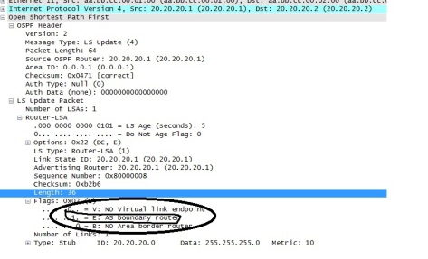
So you can see that IOU1 is generating the type 7 NSSA external LSA.

IOU1#show ip ospf database | b Type-7
Type-7 AS External Link States (Area 1)

Link ID     ADV Router   Age           Seq#       Checksum  Tag
1.1.1.0          1.1.1.1            1964    0x80000003   0x00A8C2 0

On the router IOU2 we can see both the type 7 LSA and the type 5 LSA since the NSSA ABR router IOU3 converts the type 7 to type 5 LSA.

IOU2#sh ip ospf database | b External
Type-7 AS External Link States (Area 1)

Link ID    ADV Router    Age    Seq#              Checksum Tag
1.1.1.0          1.1.1.1            37        0x80000004     0x00A6C3 0

Type-5 AS External Link States

Link ID   ADV Router    Age   Seq#           Checksum Tag
1.1.1.0         13.13.13.1      51   0x80000004 0x001A36 0

As i mentioned previously if we can analyze the external LSA’s you have the FA set by the NSSA ASBR. The ASBR choosed the highest active NSSA IP address as the FA.in this case it chose 11.11.11.1 since its higher than 10.10.10.1

IOU2#show ip ospf database nssa-external

OSPF Router with ID (12.12.12.1) (Process ID 1)

Type-7 AS External Link States (Area 1)

Routing Bit Set on this LSA in topology Base with MTID 0
LS age: 277
Options: (No TOS-capability, Type 7/5 translation, DC, Upward)
LS Type: AS External Link
Link State ID: 1.1.1.0 (External Network Number )
Advertising Router: 1.1.1.1
LS Seq Number: 80000004
Checksum: 0xA6C3
Length: 36
Network Mask: /24
Metric Type: 2 (Larger than any link state path)
MTID: 0
Metric: 20
Forward Address: 11.11.11.1
External Route Tag: 0

If we analyse the IOU3 you would have the NSSA external type 7 LSA and type 5 LSA advertised by itself.

IOU3#show ip ospf database | b External
Type-7 AS External Link States (Area 1)

Link ID       ADV Router      Age       Seq#        Checksum Tag
1.1.1.0          1.1.1.1                  382        0x80000004       0x00A6C3 0

Type-5 AS External Link States

Link ID   ADV Router      Age      Seq#          Checksum Tag
1.1.1.0         13.13.13.1        394        0x80000004      0x001A36 0

Now we will see the OSPF database of IOU4 to see which path it takes to reach 1.1.1.1 . We can see the external as advertised by IOU3 since that was the ABR which converted type 7 to  type 5.

IOU4#show ip ospf database external

OSPF Router with ID (14.14.14.1) (Process ID 1)

Type-5 AS External Link States

Routing Bit Set on this LSA in topology Base with MTID 0
LS age: 1608
Options: (No TOS-capability, DC, Upward)
LS Type: AS External Link
Link State ID: 1.1.1.0 (External Network Number )
Advertising Router: 13.13.13.1
LS Seq Number: 80000006
Checksum: 0x1638
Length: 36
Network Mask: /24
Metric Type: 2 (Larger than any link state path)
MTID: 0
Metric: 20
Forward Address: 11.11.11.1
External Route Tag: 0

In the routing table we can see that it takes the path through the NSSA ABR IOU3. Since the default external type is E2 we see 2 metrics here. The metric 20 is the metric to reach the external prefix and the forward metric is the metric to reach the Forwarding address.

So if we have FA set, the least cost to reach the FA is preferred irrespective of who is the NSSA ABR which converts the type 7 to type 5.

Now since the cost to the FA is same for IOU4 through both IOU2 and IOU3 it prefers IOU3 since that advertised the type 5.

IOU4#show ip route 1.1.1.1
Routing entry for 1.1.1.0/24
Known via “ospf 1”, distance 110, metric 20, type extern 2, forward metric 20
Last update from 13.13.13.1 on Ethernet0/3, 00:00:02 ago
Routing Descriptor Blocks:
* 13.13.13.1, from 13.13.13.1, 00:00:02 ago, via Ethernet0/3
Route metric is 20, traffic share count is 1

*** An external route with FA set will be used in the routing table only if the FA is reachable through an INTER-AREA or an INTRA- AREA**

In our case its inter-area.

IOU4#show ip route 11.11.11.1
Routing entry for 11.11.11.0/24
Known via “ospf 1”, distance 110, metric 20, type inter area
Last update from 13.13.13.1 on Ethernet0/3, 00:05:35 ago
Routing Descriptor Blocks:
* 13.13.13.1, from 13.13.13.1, 00:05:35 ago, via Ethernet0/3
Route metric is 20, traffic share count is 1

What would happen if i change the cost on IOU4 or IOU3 ? we can change the OSPF cost on E0/3 in IOU4 or E0/1 in IOU3  . i am changing the cost in IOU3 now.

IOU3(config)#int ethernet 0/1
IOU3(config-if)#ip ospf cost 40
IOU3(config-if)#
IOU3#wr m
*Dec 2 01:20:12.591: %SYS-5-CONFIG_I: Configured from console by console
IOU3#wr mem
Building configuration…

Now after the changing the cost on E0/1 in IOU3, the external route in IOU4 is taking the path through IOU2 why?

IOU4#show ip route 1.1.1.1
Routing entry for 1.1.1.0/24
Known via “ospf 1”, distance 110, metric 20, type extern 2, forward metric 30
Last update from 12.12.12.1 on Ethernet0/2, 00:00:03 ago
Routing Descriptor Blocks:
* 12.12.12.1, from 13.13.13.1, 00:00:03 ago, via Ethernet0/2
Route metric is 20, traffic share count is 1

Since the cost to the FA is 30 through E0/2 it prefers IOU2 though IOU3 generated type 5 LSA.

IOU4#show ip route 11.11.11.1
Routing entry for 11.11.11.0/24
Known via “ospf 1”, distance 110, metric 30, type inter area
Last update from 12.12.12.1 on Ethernet0/2, 00:01:56 ago
Routing Descriptor Blocks:
* 12.12.12.1, from 12.12.12.1, 00:01:56 ago, via Ethernet0/2
Route metric is 30, traffic share count is 1

As we can see the metric advertised by IOU3 to reach the FA is 40 .

LS age: 417
Options: (No TOS-capability, DC, Upward)
LS Type: Summary Links(Network)
Link State ID: 11.11.11.0 (summary Network Number)
Advertising Router: 13.13.13.1
LS Seq Number: 8000000B
Checksum: 0x3A87
Length: 28
Network Mask: /24
MTID: 0 Metric: 40

Now we are moving to IOU5 to check which route it prefers. As you can see it prefers IOU2 due to the cost to the FA is less through that path.

IOU5#show ip route 1.1.1.1
Routing entry for 1.1.1.0/24
Known via “ospf 1”, distance 110, metric 20, type extern 2, forward metric 40
Last update from 14.14.14.1 on Ethernet0/0, 00:43:02 ago
Routing Descriptor Blocks:
* 14.14.14.1, from 13.13.13.1, 00:43:02 ago, via Ethernet0/0
Route metric is 20, traffic share count is 1

IOU5#traceroute 1.1.1.1 num
Type escape sequence to abort.
Tracing the route to 1.1.1.1
VRF info: (vrf in name/id, vrf out name/id)
1 14.14.14.1 1 msec 0 msec 1 msec
2 12.12.12.1 1 msec 0 msec 1 msec
3 10.10.10.1 2 msec 2 msec 1 msec
IOU5#

“So the conclusion is if we have FA set, the least cost to the FA is preferred “.

Points to remember : 

  1. If we have Forwarding address set in the External route the least cost to the forwarding address is preferred no matter which NSSA ABR converts the type 7 to type 5 LSA
  2. The Forwarding address should be reachable through a INTER-AREA or INTRA AREA to be moved to the routing table.
  3. The Forward metric in the EXTERNAL TYPE 2 denotes the cost to the FA .
  4. In EXTERNAL TYPE 1 the cost the external network plus the cost to the FA is merged together.

PART 2 of the Forwarding address will be continued in the next post 🙂

**BGP Route-Reflector Loop Avoidance**

After OSPF and TCP, here is my first post about BGP and we are going to deal with what is Route-reflector? why do we need route-reflector and how it avoids loop?

As we all know IBGP avoid loops by not advertising routes learned from one IBGP neighbor to another IBGP neighbor  . The reason being , when IBGP sends routes from one to another they don’t add their own AS_PATH if in case the prefix being an EBGP prefix or an IBGP prefix.

so how can we scale the network?

We need to either have full mesh IBGP else we need to have something called the Route-reflector which can mitigate the IBGP loop avoidance and reflect routes received from one IBGP neighbor to another but how will you avoid loops in case of route reflector and what are the rules?

  1. Routes received from non-client will be send only to clients .
  2. Routes received from RR  clients will send to all clients as well as non-clients.
  3.  when the RR reflects the BGP updates to a client or a non-client it cant modify any path attributes it would just reflect the bgp updates received

It avoids loops with something called the CLUSTER ID AND THE ORIGINATOR ID. The Cluster-id is Router ID of the route-reflector and the Originator ID is Router ID of the router which originated the route so when a router sees their own cluster ID or the originator ID it will deny the BGP update.

Here is our scenario :

rr_client-jpeg


The Loopacks of the routers are following so the BGP identifier are the loop backs.

1.1.1.1 , 2.2.2.2 , 3.3.3.3 , 4.4.4.4 – Their respective routers name.

The IGP between them is OSPF. IOU3 advertises the prefix 13.13.13.13 and IOU4 advertises the prefix 14.14.14.14.

IOU3 and IOU4 are the RR-clients for IOU1 and IOU2 and we have IBGP between IOU1 and IOU2 also.

Here are the BGP configurations:

IOU1#show run | s bgp
router bgp 10
bgp router-id 1.1.1.1
bgp log-neighbor-changes
neighbor 10.10.10.2 remote-as 10
neighbor 10.10.10.2 route-reflector-client
neighbor 20.20.20.2 remote-as 10
neighbor 50.50.50.2 remote-as 10
neighbor 50.50.50.2 route-reflector-client

IOU2#router bgp 10
bgp router-id 2.2.2.2
bgp log-neighbor-changes
neighbor 20.20.20.1 remote-as 10
neighbor 30.30.30.2 remote-as 10
neighbor 30.30.30.2 route-reflector-client
neighbor 40.40.40.1 remote-as 10
neighbor 40.40.40.1 route-reflector-client

IOU3#show run | s bgp
router bgp 10
bgp router-id 3.3.3.3
bgp log-neighbor-changes
network 13.13.13.0 mask 255.255.255.0
neighbor 10.10.10.1 remote-as 10
neighbor 40.40.40.2 remote-as 10

IOU4#show run | s bgp
router bgp 10
bgp router-id 4.4.4.4
bgp log-neighbor-changes
network 14.14.14.0 mask 255.255.255.0
neighbor 30.30.30.1 remote-as 10
neighbor 50.50.50.1 remote-as 10

So why do we need the IOU3 to be the route-reflector client  for IOU2 and why do we need the IOU4 be the route-reflector client for IOU1?

Imagine if the link goes down IOU1 and IOU3 , IOU1 wont have access to the network 13.13.13.13 if IOU3 is not the RR_CLIENT for IOU2 , since its the RR_CLIENT now, as per rule 2 ,routes received from the RR_client can be given to clients as well as non-client so IOU2 will reflect the route to IOU1 as well as IOU4 and moreover IOU4 will also recieve the route from IOU1 since its a RR_CLIENT for IOU1 too and the same goes with IOU2 too, if the link goes down between IOU2 and IOU4 ,it wont have to access to 14.14.14.14 unless IOU4 is the RR_CLIENT for IOU1 as well.

As you can see the output in IOU1 and IOU2 both have redundant routes to 13.13.13.13 as well as 14.14.14.14 though they pick the BEST Path according to the best path algorithm.

“The other solution would IOU2 will be RR-client for IOU1 and viceversa if we dont need IOU3 as the RR_CLIENT for IOU2 and IOU4 as the RR _client for IOU1 in this case we would hit the rule 1 as updates from non-client will be send to only clients”

IOU1#show ip bgp 13.13.13.13
BGP routing table entry for 13.13.13.0/24, version 2
Paths: (2 available, best #2, table default)
Advertised to update-groups:
1 2
Refresh Epoch 1
Local
40.40.40.1 (metric 20) from 20.20.20.2 (2.2.2.2)
Origin IGP, metric 0, localpref 100, valid, internal
Originator: 3.3.3.3, Cluster list: 2.2.2.2
rx pathid: 0, tx pathid: 0
Refresh Epoch 1
Local, (Received from a RR-client)
10.10.10.2 from 10.10.10.2 (3.3.3.3)
Origin IGP, metric 0, localpref 100, valid, internal, best
rx pathid: 0, tx pathid: 0x0

IOU2#show ip bgp 14.14.14.14
BGP routing table entry for 14.14.14.0/24, version 5
Paths: (2 available, best #1, table default)
Advertised to update-groups:
2 3
Refresh Epoch 2
Local, (Received from a RR-client)
30.30.30.2 from 30.30.30.2 (4.4.4.4)
Origin IGP, metric 0, localpref 100, valid, internal, best
rx pathid: 0, tx pathid: 0x0
Refresh Epoch 1
Local
50.50.50.2 (metric 20) from 20.20.20.1 (1.1.1.1)
Origin IGP, metric 0, localpref 100, valid, internal
Originator: 4.4.4.4, Cluster list: 1.1.1.1
rx pathid: 0, tx pathid: 0

So lets see by shutting down the link between IOU1 and IOU3

IOU1(config)#int et 1/0
IOU1(config-if)#shu
IOU1(config-if)#shutdown
IOU1(config-if)#
IOU1#
*Oct 14 15:53:40.706: %OSPF-5-ADJCHG: Process 1, Nbr 10.10.10.2 on Ethernet1/0 from FULL to DOWN, Neighbor Down: Interface down or detached
*Oct 14 15:53:41.247: %SYS-5-CONFIG_I: Configured from console by console
IOU1#cle
IOU1#clear ip bgp
*Oct 14 15:53:42.703: %LINK-5-CHANGED: Interface Ethernet1/0, changed state to administratively down
*Oct 14 15:53:43.704: %LINEPROTO-5-UPDOWN: Line protocol on Interface Ethernet1/0, changed state to down

IOU1#clear ip bgp 10.10.10.2
*Oct 14 15:53:56.667: %BGP-5-ADJCHANGE: neighbor 10.10.10.2 Down User reset
*Oct 14 15:53:56.667: %BGP_SESSION-5-ADJCHANGE: neighbor 10.10.10.2 IPv4 Unicast topology base removed from session User reset

IOU1#show ip bgp summary | s 10.10.10.2
10.10.10.2 4 10 0 0 1 0 0 00:01:09 Idle

But you can still see we are able to ping 13.13.13.13

IOU1#ping 13.13.13.13
Type escape sequence to abort.
Sending 5, 100-byte ICMP Echos to 13.13.13.13, timeout is 2 seconds:
!!!!!
Success rate is 100 percent (5/5), round-trip min/avg/max = 1/1/1 ms
IOU1#traceroute 13.13.13.13
Type escape sequence to abort.
Tracing the route to 13.13.13.13
VRF info: (vrf in name/id, vrf out name/id)
1 20.20.20.2 2 msec 1 msec 1 msec
2 40.40.40.1 1 msec 1 msec 1 msec
IOU1#show ip bgp 13.13.13.13
BGP routing table entry for 13.13.13.0/24, version 4
Paths: (1 available, best #1, table default)
Advertised to update-groups:
1
Refresh Epoch 1
Local
40.40.40.1 (metric 20) from 20.20.20.2 (2.2.2.2)
Origin IGP, metric 0, localpref 100, valid, internal, best
Originator: 3.3.3.3, Cluster list: 2.2.2.2
rx pathid: 0, tx pathid: 0x0

This is called nested Route-reflectors where even if one RR goes down the other Route-reflector can take care of the data forwarding.

As we can see when it passes through the RR, it adds the cluster ID and the originator ID.

Imagine if we have 2 lakh routes and if we have NESTED RR_CLIENTS , the routing table will be cpu intensive since IOU1 and IOU2 would have redundant routes like what we see for 13.13.13.13.so what can be done to avoid it?

We can have the same cluster -ID in both IOU1 and IOU2 so in this case what will happen? Lets see the advantages and disadvantages?

Lets create a same the cluster id for IOU1 and IOU2.

IOU1#show run | s bgp
router bgp 10
bgp router-id 1.1.1.1
bgp cluster-id 100.100.100.100
bgp log-neighbor-changes

IOU2#show run | s bgp
router bgp 10
bgp router-id 2.2.2.2
bgp cluster-id 100.100.100.100

Lets see how many routes now IOU1 has for 13.13.13.13 ?

IOU1#show ip bgp 13.13.13.13
BGP routing table entry for 13.13.13.0/24, version 8
Paths: (1 available, best #1, table default)
Advertised to update-groups:
3 5
Refresh Epoch 2
Local, (Received from a RR-client)
10.10.10.2 from 10.10.10.2 (3.3.3.3)
Origin IGP, metric 0, localpref 100, valid, internal, best
rx pathid: 0, tx pathid: 0x0

It has only one path now through the direct path why?  since we configured the same cluster id on both IOU1 and IOU2, when IOU2 reflects the prefix 13.13.13.13 to IOU1 ,IOU1 will reject the update because it would see the same cluster ID.

Here is the debug output of the same.

*Oct 14 16:09:29.671: BGP(0): 20.20.20.2 rcv UPDATE about 13.13.13.0/24 — DENIED due to: reflected from the same cluster;
*Oct 14 16:09:29.671: BGP: 20.20.20.2 RR in same cluster. Reflected update dropped

So the advantage here is we have only one path in the routing table but the disadvantage is when the link between IOU1 and IOU3 goes down IOU1 cant reach the prefix 13.13.13.13 since it denies the update from IOU2.

In my next post in BGP will write about potential loops in RR if the physical topology and the control plane are different?


Mystery behind OSPF DR/BDR election?

In the OSPF DR/BDR election which one gets elected first the DR or the BDR?

Lets check that out in this post its all about DR/BDR.

Before we proceed to post ,the following are the critical points of DR/BDR in OSPF:

  1. The Router with the highest priority becomes the DR and the second highest becomes the BDR
  2. If the priority is same ,then the highest router-id becomes the DR and the second best becomes the BDR.
  3. If you configure a router with a priority as 0 it will be never become the DR/BDR.
  4. There is no preempt in DR/BDR ,so if a router with a highest priority comes into the network after the DR/BDR is elected it will never become the DR until the ospf neighbhorship is teared down /or shut down of the ospf interfaces or a reload of all routers and bringing up the router with the highest priority first.
  5. The DROTHER ( routers which are not DR/BDR) will establish full adjacency only with the DR/BDR . Hence with the other routers the adjacency will only be 2-way .
  6. The existence of DR/BDR came into picture in multi-access  broadcast networks to avoid unnecessary flooding of updates to all routers in the network .
  7. so the DROTHER routers when they want to send a LSA update to the network ,they send it to 224.0.0.6 so that only the DR/BDR receives it and they will use the well know multicast address of 224.0.0.5 to relay the LSA update to others.

So Here is our scenario:

screenshot-jpeg

As always i configure ospf on the interfaces:

IOU2#show run int ethernet 0/0
Building configuration…
Current configuration : 105 bytes
interface Ethernet0/0
ip address 10.10.10.1 255.255.255.0
ip ospf priority 40
ip ospf 1 area 0
end

IOU3#sh run int ethernet 0/1
Building configuration…
Current configuration : 105 bytes
interface Ethernet0/1
ip address 10.10.10.2 255.255.255.0
ip ospf priority 60
ip ospf 1 area 0
end

IOU4#show run int et 0/2
Building configuration…
Current configuration : 104 bytes
interface Ethernet0/2
ip address 10.10.10.3 255.255.255.0
ip ospf priority 0
ip ospf 1 area 0
end

So as per the priorities configured  IOU4 will never become a DR/BDR since the configured priority is 0 and IOU3  or IOU2 should be come as the DR or BDR depending on which one comes up first. I bought IOU3 first , then the IOU2 then the IOU4. so IOU3 should be the DR and IOU2 should be the BDR.

So as soon as we unshut the interfaces and bring OSPF,there is something called the “wait timer in OSPF which is 40 seconds until which the routers would never claim that they are the DR/BDR, before the wait timer expires if it receives an hello with the DR/BDR it will accept the hellos and agree to the DR/BDR as there is no preempt”

Since i turned on IOU3 first , when IOU3 send the hellos you can see the DR/BDR is still 0.0.0.0 /0.0.0.0 because it is still in the wait timer of 40 seconds and the CLI output too.

*Oct 4 03:21:30.976: %LINK-3-UPDOWN: Interface Ethernet0/1, changed state to up
*Oct 4 03:21:31.977: %LINEPROTO-5-UPDOWN: Line protocol on Interface Ethernet0/ 1, changed state to up
*Oct 4 03:21:31.977: OSPF-1 ADJ Et0/1: Route adjust notification: UP/UP
*Oct 4 03:21:31.977: OSPF-1 ADJ Et0/1: Interface going Up
*Oct 4 03:21:31.977: OSPF-1 ADJ Et0/1: Interface state change to UP, new ospf state WAIT
IOU3(config-if)#do show ip ospf inter | s Wait
Timer intervals configured, Hello 10, Dead 40, Wait 40, Retransmit 5
oob-resync timeout 40
Hello due in 00:00:07
Wait time before Designated router selection 00:00:38

IOU3(config-if)#do show ip ospf inter | s Wait
Timer intervals configured, Hello 10, Dead 40, Wait 40, Retransmit 5
oob-resync timeout 40
Hello due in 00:00:06
Wait time before Designated router selection 00:00:36

IOU3(config-if)#do show ip ospf inter | s Wait
Timer intervals configured, Hello 10, Dead 40, Wait 40, Retransmit 5
oob-resync timeout 40
Hello due in 00:00:03
Wait time before Designated router selection 00:00:05

IOU3(config-if)#
*Oct 4 03:22:09.771: OSPF-1 ADJ Et0/1: 2 Way Communication to 10.10.10.3, sta te 2WAY
IOU3(config-if)#
*Oct 4 03:22:11.977: OSPF-1 ADJ Et0/1: end of Wait on interface
*Oct 4 03:22:11.977: OSPF-1 ADJ Et0/1: DR/BDR election
*Oct 4 03:22:11.977: OSPF-1 ADJ Et0/1: Elect BDR 10.10.10.2
*Oct 4 03:22:11.977: OSPF-1 ADJ Et0/1: Elect DR 10.10.10.2
*Oct 4 03:22:11.977: OSPF-1 ADJ Et0/1: Elect BDR 10.10.10.1

As you can see above since it saw the HELLO’s from IOU2 it selects the BDR first 

IOU2(config-if)#
*Oct 4 03:21:56.577: %LINK-3-UPDOWN: Interface Ethernet0/0, changed state to up
*Oct 4 03:21:57.577: %LINEPROTO-5-UPDOWN: Line protocol on Interface Ethernet0/ 0, changed state to up
*Oct 4 03:21:57.577: OSPF-1 ADJ Et0/0: Route adjust notification: UP/UP
*Oct 4 03:21:57.577: OSPF-1 ADJ Et0/0: Interface going Up
*Oct 4 03:21:57.578: OSPF-1 ADJ Et0/0: Interface state change to UP, new ospf state WAIT
IOU2(config-if)#
*Oct 4 03:22:00.744: OSPF-1 ADJ Et0/0: 2 Way Communication to 10.10.10.2, sta te 2WAY
IOU2(config-if)#

And now since IOU2 saw the hellos before its WAIT TIMER expired it will elect the DR as IOU3.


drbdr

So as you saw the Router which came online first became the DR and the second best came the BDR as they wait for 40Second timer and claim the DR/BDR status.

Here comes the fun part we have all read that in DR/BDR there is no preempt ? 

Yes but not exactly ? How come?

Since i said there is a wait timer of 40s before any router claims itself as DR or BDR there is always a guarded preemptive feature that with in 40 Seconds there is always a preempt no matter which router comes up first if you change the priority on the fly..as you can see the outputs below..

I brought up IOU3 first so as per logic IOU3 should come up as DR.

IOU3(config-if)#no shu
IOU3(config-if)#no shutdown
IOU3(config-if)#
*Oct 4 03:48:38.364: %LINK-3-UPDOWN: Interface Ethernet0/1, changed state to up
*Oct 4 03:48:39.365: %LINEPROTO-5-UPDOWN: Line protocol on Interface Ethernet0/1, changed state to up
*Oct 4 03:48:39.365: OSPF-1 ADJ Et0/1: Route adjust notification: UP/UP
*Oct 4 03:48:39.365: OSPF-1 ADJ Et0/1: Interface going Up
*Oct 4 03:48:39.365: OSPF-1 ADJ Et0/1: Interface state change to UP, new ospf state WAIT
*Oct 4 03:48:39.365: OSPF-1 ADJ Et0/1: 2 Way Communication to 10.10.10.3, state 2WAY
IOU3(config-if)#do show ip ospf inter | s Wait
Timer intervals configured, Hello 10, Dead 40, Wait 40, Retransmit 5
oob-resync timeout 40
Hello due in 00:00:01
Wait time before Designated router selection 00:00:32

And after some after some time before the time wait expires i did no shut of the interface in IOU2 and changed the priority to 70.

IOU2(config-if)#do debug ip ospf adj
OSPF adjacency debugging is on
IOU2(config-if)#no shutdown
IOU2(config-if)#
*Oct 4 03:48:41.539: %LINK-3-UPDOWN: Interface Ethernet0/0, changed state to up
*Oct 4 03:48:42.539: %LINEPROTO-5-UPDOWN: Line protocol on Interface Ethernet0/0, changed state to up
*Oct 4 03:48:42.539: OSPF-1 ADJ Et0/0: Route adjust notification: UP/UP
*Oct 4 03:48:42.539: OSPF-1 ADJ Et0/0: Interface going Up
*Oct 4 03:48:42.539: OSPF-1 ADJ Et0/0: Interface state change to UP, new ospf state WAIT
IOU2(config-if)#
*Oct 4 03:48:42.541: OSPF-1 ADJ Et0/0: 2 Way Communication to 10.10.10.3, state 2WAY
IOU2(config-if)#
*Oct 4 03:48:48.542: OSPF-1 ADJ Et0/0: 2 Way Communication to 10.10.10.2, state 2WAY
IOU2(config-if)#ip ospf pro
IOU2(config-if)#ip ospf prio 70


As you can see finally within the timer since there was a better DR in the network the DR/BDR changed

*Oct 4 03:49:31.213: OSPF-1 ADJ Et0/1: Neighbor change event
*Oct 4 03:49:31.213: OSPF-1 ADJ Et0/1: DR/BDR election
*Oct 4 03:49:31.213: OSPF-1 ADJ Et0/1: Elect BDR 10.10.10.2
*Oct 4 03:49:31.213: OSPF-1 ADJ Et0/1: Elect DR 10.10.10.1
*Oct 4 03:49:31.213: OSPF-1 ADJ Et0/1: Elect BDR 10.10.10.2
*Oct 4 03:49:31.213: OSPF-1 ADJ Et0/1: Elect DR 10.10.10.1
*Oct 4 03:49:31.213: OSPF-1 ADJ Et0/1: DR: 10.10.10.1 (Id) BDR: 10.10.10.2 (Id)

ON IOU2:

*Oct 4 03:49:22.540: OSPF-1 ADJ Et0/0: end of Wait on interface
*Oct 4 03:49:22.540: OSPF-1 ADJ Et0/0: DR/BDR election
*Oct 4 03:49:22.540: OSPF-1 ADJ Et0/0: Elect BDR 10.10.10.1
*Oct 4 03:49:22.540: OSPF-1 ADJ Et0/0: Elect DR 10.10.10.1
*Oct 4 03:49:22.540: OSPF-1 ADJ Et0/0: Elect BDR 10.10.10.2
*Oct 4 03:49:22.540: OSPF-1 ADJ Et0/0: Elect DR 10.10.10.1
*Oct 4 03:49:22.540: OSPF-1 ADJ Et0/0: DR: 10.10.10.1 (Id) BDR: 10.10.10.2 (Id)
*Oct 4 03:49:22.540: OSPF-1 ADJ Et0/0: Nbr 10.10.10.2: Prepare dbase exchange
*Oct 4 03:49:22.540: OSPF-1 ADJ Et0/0: Send DBD to 10.10.10.2 seq 0xF9 opt 0x52 flag 0x7 len 32

IOU3#show ip ospf neighbor

Neighbor ID  Pri       State                      Dead Time              Address             Interface
10.10.10.1       70        FULL/DR                00:00:36              10.10.10.1             Ethernet0/1
10.10.10.3      0           FULL/DROTHER   00:00:35             10.10.10.3             Ethernet0/1
IOU3#

Again when i change the priorities back and shut the IOU3 , brought up IOU2 ,then the IOU2 with higher priority since the router recieved an hello before the wait timer IOU2 became the DR.

*Oct 4 07:09:47.628: OSPF-1 ADJ Et0/1: Backup seen event before WAIT timer- This is the crux of this post.
*Oct 4 07:09:47.628: OSPF-1 ADJ Et0/1: DR/BDR election – 
*Oct 4 07:09:47.628: OSPF-1 ADJ Et0/1: Elect BDR 10.10.10.2
*Oct 4 07:09:47.628: OSPF-1 ADJ Et0/1: Elect DR 10.10.10.1
*Oct 4 07:09:47.628: OSPF-1 ADJ Et0/1: Elect BDR 10.10.10.2
*Oct 4 07:09:47.628: OSPF-1 ADJ Et0/1: Elect DR 10.10.10.1

So the summary of the post is as follows:

  1. Unless the time wait which is of 40 seconds expires , the routers are not going to claim them selves as DR/BDR and before the 40 seconds if there is a hello from the other router , depending upon its priority and router id it can claim itself too be the DR/BDR
  2. After the 40 second interval for example if you are trying to bring the a router IOU5 with the highest priority it will still be a DROTHER
  3. The BDR always gets elected first since that will be the next DR.


Thanks and Regards,

Avinash R


***TCP MSS *** How it really works?

So after the first 2 posts on OSPF just wanted to dive into TCP then go back to OSPF else it would be over kill of that beautiful link state protocol 🙂

We all know that TCP is connection oriented and it works  by establishing a three-way-handshake between the client and the server. I am always fantasized to learn more about TCP on how it works in the internet other than the three-way handshake between them.

So when it comes to packet structure of the TCP you can only see the MSS in the options section of the header which is a integral part of how TCP really works in this world and “as contrary to the belief that MSS is always negotiated between the client and the server , it is really not negotiated between the hosts , as you can see them below when i explain it with a scenario and a packet capture .The TCP MSS is always send by the client-server during the TCP 3-way hand shake”

So what is TCP MSS? 

“As we all know TCP does transmission of data in segments the MSS is the largest amount of data the TCP can sen in a ONE segment.” For example if you have to send a chunk of 2000 bytes of data to the client , if the MSS is 1460 , you can only send 1460 bytes of data in one segment and the other 540 bytes of data in the 2nd segment and it keeps of track as you know by SEQ and ACK numbers.

So how is TCP MSS calculated ? 

“The TCP MSS is always the MTU minus the IP header + TCP header (MSS=MTU-IP Header-TCP header)

Hence if the MTU is 1500 , the TCP MSS will be 1460 since IP header is 20 and the TCP header is 20.


So lets see a real time example of how a TCP works now:

“Since we cant set the MTU in GNS3 the default MTU is 1500”.

tcpmss-jpeg


IOU1,IOU2 and IOU3 are in same OSPF area 0 and we are going to do a  telnet from IOU2 to IOU3 to simulate TCP traffic.

As you can see PING  and TELNET works fine.

IOU1#ping 20.20.20.2
Type escape sequence to abort.
Sending 5, 100-byte ICMP Echos to 20.20.20.2, timeout is 2 seconds:
!!!!!
Success rate is 100 percent (5/5), round-trip min/avg/max = 1/1/2 ms

IOU1#telnet 20.20.20.2
Trying 20.20.20.2 … Open
User Access Verification
Username: cisco
Password:
IOU3>en
Password:
IOU3#exit
[Connection to 20.20.20.2 closed by foreign host]
IOU1#

Now you will see the MTU on IOU1 and IOU3.

IOU1#show int ethernet 0/0 | s MTU
MTU 1500 bytes, BW 10000 Kbit/sec, DLY 1000 usec,
reliability 255/255, txload 1/255, rxload 1/255

IOU3#show int ethernet 0/1 | s MTU
MTU 1500 bytes, BW 10000 Kbit/sec, DLY 1000 usec,
reliability 255/255, txload 1/255, rxload 1/255

So lets a look the packet on what is the MSS set when IOU1 initiates telnet to IOU3 and vice-versa? 

Since the default TCP value is 536 when cisco initiates TCP connection to a server we can see the outgoing MSS from IOU1 to be 536 .It is 576 (the mimimum MTU required for a router – 20 IP header-20 TCP header) hence  when IOU3 responds back it also responds back with same default MSS which 536.

tcpmsspcap


Though we cant change the MTU in the interface we can still modify the TCP MSS in an interface . So i am trying to modify the value in IOU3 when it responds back to IOU1 tcp requests.

IOU3(config)#int ethernet 0/1
IOU3(config-if)#ip tcp
IOU3(config-if)#ip tcp ad
IOU3(config-if)#ip tcp adjust-mss ? —————>

“we can clearly see that it cant exceed 1460 because the MTU is 1500 so the TCP MSS is 1500-20-20=1460 .
<500-1460> Maximum segment size in bytes”

IOU3(config-if)#ip tcp adjust-mss 1460

IOU3#show run int ethernet 0/1
Building configuration…
Current configuration : 108 bytes
!
interface Ethernet0/1
ip address 20.20.20.2 255.255.255.0
ip tcp adjust-mss 1460
ip ospf 1 area 0
end

So we can see the packet capture again from IOU3 to IOU1 ?

Since IOU1 is sending only TCP MSS  of 536 when IOU3 responds it can only send data equal too or less than the MSS set by IOU1 in a segment.

tcpmssiou3
As you can see the MSS is 536.

Now lets set the IP TCP ADJUST MSS to 1460
IOU1(config)#int ethernet 0/0
IOU1(config-if)#ip ad
IOU1(config-if)#ip adju
IOU1(config-if)#ip tcp
IOU1(config-if)#ip tcp ad
IOU1(config-if)#ip tcp adjust-mss 1460
IOU1(config-if)#
IOU1#wr mem
Building configuration…
IOU1#show run int ethernet 0/0
Building configuration…
Current configuration : 108 bytes
!
interface Ethernet0/0
ip address 10.10.10.1 255.255.255.0
ip tcp adjust-mss 1460
ip ospf 1 area 0
end

I will do a telnet again from IOU1 to IOU3.

IOU1#telnet 20.20.20.2
Trying 20.20.20.2 … Open
User Access Verification
Username: cisco
Password:
IOU3>en
Password:
IOU3#
IOU3#
IOU3#exit
[Connection to 20.20.20.2 closed by foreign host]
IOU1#
IOU1#
IOU1#

Lets the packet capture now:

1460-1


we can see that the MSS set by IOU1 is 1460 and Lets what IOU3 responds back.

1460-2


So how will the hosts behind the routers know the MTU of the path to the server in the internet ?

Thats where the PMTU discovery plays a role in it.. i will write another post on how PATH-MTU discovery works.

So the summary is 

  •  The TCP MSS is one of the parameters in the tcp options field which is send by the client-server during the 3 -way handshake.
  • It is the largest amount of data which it can send in a single segment to any hosts
  • Its not necessary that the MSS should be same between the 2 hosts
  • They agree to the optimum value between the 2 if the mss is different.


Regards,

Avinash R

Summary ASB Type4 LSA Part-2 (NSSA)

As we continue our series on Summary ASB LSA 4 we look at LSA4 in NSSA(Not-s0-Stubby-Area).

we all know that the stubby area allows only Router LSA( type1 LSA), network LSA(type2 LSA) and the Summary LSA ( type3 LSA) , the only difference in NSSA is, it allows and generates type 7 LSA.

We saw why we need LSA4 , who generates and why it generated etc ..in the last post, this post involves what happens when we have NSSA AREA.

Here is our scenario.

newonelsa-jpeg


Here are the configurations .  I configure OSPF in the interfaces.

router ospf 1
area 1 nssa
IOU1#show run int et
IOU1#show run int ethernet 0/0
Building configuration…
Current configuration : 84 bytes
interface Ethernet0/0
ip address 10.10.10.1 255.255.255.0
ip ospf 1 area 1
end

IOU2#show run | s ospf
ip ospf 1 area 1
ip ospf 1 area 0
router ospf 1
area 1 nssa
IOU2#show run int et 0/0
Building configuration…
Current configuration : 84 bytes
interface Ethernet0/0
ip address 10.10.10.2 255.255.255.0
ip ospf 1 area 1
end
IOU2#show run int et 0/1
Building configuration…
Current configuration : 84 bytes
interface Ethernet0/1
ip address 20.20.20.1 255.255.255.0
ip ospf 1 area 0
end

IOU3#Show run | s ospf
ip ospf 1 area 0
router ospf 1
IOU3#show run int et 0/1
Building configuration…
Current configuration : 84 bytes
!
interface Ethernet0/1
ip address 20.20.20.2 255.255.255.0
ip ospf 1 area 0
end

As we can see there is nothing redistributed or injected in IOU1 so it doesnt generate LSA7.

IOU1#show ip ospf database | b External
IOU1#

  As per the configuration,diagram IOU2 is the NSSA ABR So can we expect the IOU2 to be ASBR for the rest of the network?

Yes its the ASBR for the rest of the network since the NSSA ABR always translates the type 7 to type 5 unless the P-bit is cleared or unless the other NSSA ABR in multiple ABR scenarios, translates type 7 to type 5 in virtue of highest IP address.

we will come to know whats about the P – bit a bit later in the NSSA FA series .

There is no LSA type 7 from IOU1 as we saw above!!! will IOU2 still be the ASBR for the rest of the network?

Absolutely , Though there is no type 7 LSA from IOU1 , since its NSSA , the NSSA ABR IOU2 takes the role of the ASBR and sets the E bit to its neighbors indicating thats the ASBR.

  • Here is the packet snippet from IOU2 to IOU3. we can see that IOU2 sets the E bit in router LSA as well as the B-bit indicating that its the ABR too.

nssaabrebit


we did see in the previous posts that with in the same area if we have ASBR we don’t need the type4 LSA because it reaches through the router LSA so IOU3 doesnt need one .

“what happens now when we connect another router to IOU3 in some other area will that router see an type 4 LSA ” ?

Lets do that and see what happens ..

modifiedwithanotherrouter-jpeg


Modified configuration of IOU3 since we added IOU4 .

IOU3#show run int et 0/0
Building configuration…
Current configuration : 84 bytes
!interface Ethernet0/0
ip address 30.30.30.1 255.255.255.0
ip ospf 1 area 2
end
IOU3#

IOU4#show run | s ospf
ip ospf 1 area 2
router ospf 1
IOU4#show run int et 0/0
Building configuration…
Current configuration : 84 bytes
interface Ethernet0/0
ip address 30.30.30.2 255.255.255.0
ip ospf 1 area 2
end

“After the neighborship is up , we can see type 4 LSA generated by IOU3 with the link ID as IOU2 since IOU is the ASBR ( converts type 7 to type5).”

IOU4#show ip ospf database | b Summary ASB
Summary ASB Link States (Area 2)

Link ID          ADV Router     Age          Seq#         Checksum
20.20.20.1     20.20.20.2        443             0x80000001   0x0015A1
IOU4#

Conclusion:

  1. Though we don’t redistribute anything or we dont see any external network injected or generated in  NSSA , the NSSA ABR will take the role as the ASBR for the rest of the network and the ABR will generate the type4 LSA for the other networks.

Next in series will be the impact of FA in NSSA , Does FA modify external path selection ?what happens if we suppress FA ? etc..how does the ABR choose the best path to the external network in NSSA?

Tune in ..:)

Thanks and regards,
Avinash R

All about Summary ASBR LSA4

Why do we need LSA4? Who generates it? Does it get generated with in Area 0? Do you always need LSA4? Can you reach the external network without LSA4?

what happens if we have NSSA and what if it doesn’t generate any LSA7 ? Do we still have LSA4?
Here are the answers..

My first scenario would be the following:

As you can see IOU1 and IOU2 are in AREA 1 and IOU2 and IOU3 are in AREA 0 and I am redistributing  only Loopback1 in IOU1  instead of redistributing all the connected interfaces.

updatedone-jpeg


Configurations :

I have configured the OSPF process and the area in the interfaces.

IOU1:
router ospf 1
redistribute connected subnets route-map test

IOU1#show run int lo 1
Building configuration…

Current configuration : 61 bytes
!
interface Loopback1
ip address 1.1.1.1 255.255.255.0
end

IOU1#show route-map test
route-map test, permit, sequence 10
Match clauses:
ip address prefix-lists: test
Set clauses:
Policy routing matches: 0 packets, 0 bytes

IOU1#show ip prefix-list test
ip prefix-list test: 1 entries
seq 5 permit 1.1.1.0/24
IOU1#show run int ethernet 0/0
interface Ethernet0/0
ip address 20.20.20.1 255.255.255.0
ip ospf 1 area 1
end

IOU2:
show run int ethernet 0/0
interface Ethernet0/0
ip address 20.20.20.2 255.255.255.0
ip ospf 1 area 1
end
show run int ethernet 0/1
interface Ethernet0/1
ip address 10.10.10.1 255.255.255.0
ip ospf 1 area 0
end

As you can see IOU 1 is generating LSA 5 and you can see those LSA’s in IOU2 as well as IOU3

IOU1#show ip ospf database | B External
Type-5 AS External Link States

Link ID  ADV Router    Age       Seq#              Checksum Tag
1.1.1.0     20.20.20.1        1517    0x80000002       0x00D985 0
IOU2#show ip ospf database | B External
Type-5 AS External Link States
Link ID ADV Router Age   Seq#        Checksum Tag
1.1.1.0 20.20.20.1    1680 0x80000002   0x00D985 0

IOU3#show ip ospf database | B External
Type-5 AS External Link States

Link ID ADV Router Age      Seq#        Checksum Tag
1.1.1.0 20.20.20.1     1720 0x80000002 0x00D985 0

Now how will IOU2 and IOU3 know how to reach the ASBR and who is the ASBR? Here it is.

Since IOU1 redistributed a Loopback, it is the ASBR and thus it generated LSA5 . Hence when it sends the ROUTER LSA , the LSA type 1 it sets the E bit and sends indicating external capability that the advertising router is a ASBR hence by virtue of that IOU2 will come to know that IOU1 is the ASBR .

And here is the packet capture snippet of router LSA1 send by IOU1.

lsa4ebit


As you can see that when IOU1 (20.20.20.1) sends the router LSA it sets the E bit and sends which indicates that it is the ASBR .

There we go, we got the answer on how IOU2 can reach the external prefix ?

since the router IOU2 sees that IOU1 is the ASBR through Router LSA it doesn’t need LSA type4 to reach the external prefix.
We can clearly see the ospf database that there is no summary ASBR for area 1.

It is only for AREA 0.

IOU2#show ip ospf database asbr-summary
OSPF Router with ID (20.20.20.2) (Process ID 1)
Summary ASB Link States (Area 0)
LS age: 1113
Options: (No TOS-capability, DC, Upward)
LS Type: Summary Links(AS Boundary Router)
Link State ID: 20.20.20.1 (AS Boundary Router address)
Advertising Router: 20.20.20.2
LS Seq Number: 80000006
Checksum: 0xBA6
Length: 28
Network Mask: /0
MTID: 0 Metric: 10

Now how do IOU3 comes to know the existence of ASBR in the network so that it can reach the external prefix and why should it know the ASBR to reach 1.1.1.1?
The answer is:

Whenever an external LSA is generated by the the ASBR unless and until its is NSSA ASBR the Forwarding address is always set to 0.0.0.0 or when FA is suppressed or when we redistribute static routes and advertise the next-hop’s subnet, so when IOU3 receives the external LSA it sees the FA as 0.0.0.0 and it should know where it needs to forward the packet to reach 1.1.1.1 so it should know the ASBR thus summary ASB comes into picture.

IOU3#show ip ospf database external
OSPF Router with ID (10.10.10.2) (Process ID 1)
Type-5 AS External Link States

Routing Bit Set on this LSA in topology Base with MTID 0
LS age: 375
Options: (No TOS-capability, DC, Upward)
LS Type: AS External Link
Link State ID: 1.1.1.0 (External Network Number )
Advertising Router: 20.20.20.1
LS Seq Number: 80000005
Checksum: 0xD388
Length: 36
Network Mask: /24
Metric Type: 2 (Larger than any link state path)
MTID: 0
Metric: 20
Forward Address: 0.0.0.0
External Route Tag: 0

Since it is the job of a backbone area to always generate summary ASB (LSA4) when there is ASBR in the network, the IOU2 generates the summary ASB LSA4 with the advertising router id as itself (20.20.20.2) and the Link ID as the ASBR which is 20.20.20.1 as stated above.

Here is the output from IOU3.

IOU3#show ip ospf database asbr-summary
OSPF Router with ID (10.10.10.2) (Process ID 1)
Summary ASB Link States (Area 0)

Routing Bit Set on this LSA in topology Base with MTID 0
LS age: 1501
Options: (No TOS-capability, DC, Upward)
LS Type: Summary Links(AS Boundary Router)
Link State ID: 20.20.20.1 (AS Boundary Router address)
Advertising Router: 20.20.20.2
LS Seq Number: 80000006
Checksum: 0xBA6
Length: 28
Network Mask: /0
MTID: 0 Metric: 10
So the conclusion is , the summary ASB LSA4 is always generated by the ABR and the existence of an ASBR in a network is indicated or identified by the E bit set in the router LSA.  so what happens when AREA 0 is the ABR as well as the ASBR ? Yes still you dont need LSA4 inside AREA 0 since through router lsa we will come to know about ASBR.

What happens with LSA4 in NSSA?

Tune into i love networking for the next series of LSA4 in NSSA..


This site is all about networking in depth in terms of packet captures ,analysis of bits and bytes in the packet capture ..I have created this word press to deliver what i can and what i can learn further by interacting with all the networking folks in the world ..